23.6 Walkthrough: Creating Your Own Shapes
You can create your own shapes and include them in your own sheet
simply be defining the shapes in XML (using a subset of
SVG, the scalable vector graphics format based on XML).
Installing a new shape is simply a matter of installing it into
~/.dia/shapes.
23.6.1 Simple Example
A shape consists of at least a name and a SVG element. That is, every shape, at a minimum, has a name and a description:
<?xml version="1.0"?>

<shape xmlns="http://www.daa.com.au/~james/dia-shape-ns"
       xmlns:svg="http://www.w3.org/2000/svg">
  <name>Sample - Minimal Shape</name>
  <svg:svg width="10" height="10">
    <svg:polygon points="0,0 10,0 5,10"/>
  </svg:svg>
</shape>
You can place this in a subdirectory of your own dia shapes
directory, perhaps called Sample as in
~/.dia/shapes/Sample/minimal.shape. The actual filename in
which the shape is stored (minimal.shape) is not so
important—dia will find the file.
Now you need to create a sheet into which this shape is placed. Again,
a sheet is specified using XML. This example is placed in the file
~/.dia/sheets/Sample.sheet:
<?xml version="1.0" encoding="iso-8859-1"?>
<sheet xmlns="http://www.lysator.liu.se/~alla/dia/dia-sheet-ns">
<name>Sample</name>
<description>A collection of sample shapes.</description>
<contents>
<object name="Sample - Minimal Shape">
<description>The most minimal of shapes</description>
</object>
</contents>
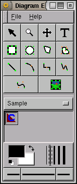
</sheet>Now start up dia and you should see this new sheet, called
Sample, containing a single button with a default icon.
 %
%
You can now create a new canvas and add this shape to your canvas. Note that dia takes care of the resizing of the shape and the other characteristics.
The XML describing the shape begins with the usual xml meta
element followed the actual shape element, identifying the
appropriate XML namespaces (xmlns). The shape has a unique
name used to identify the shape by dia. Next we have the
actual SVG description of the shape which is 10 by 10 in size
 %
(actually these are ignored by dia but are required by the
SVG format), and consisting of a single polygon. The shape is a simple
triangle (a polygon with three points) pointing downwards. The polygon
is drawn from the top left corner (0,0) to the top right (10,0) then
to the bottom middle (5,10) and then back to the top left to finish
off the polygon.
%
(actually these are ignored by dia but are required by the
SVG format), and consisting of a single polygon. The shape is a simple
triangle (a polygon with three points) pointing downwards. The polygon
is drawn from the top left corner (0,0) to the top right (10,0) then
to the bottom middle (5,10) and then back to the top left to finish
off the polygon.
The XML for the sheet then identifies this shape as belonging to the Sample sheet, which contains just one object, the Sample - Minimal Shape shape. The description for the object is used as the tooltip for the resulting button.
23.6.2 Shape Elements
An icon can be associated with the shape through the icon
element. An example is:
![]() %
which comes after the
%
which comes after the name element. The specified X pixmap
file is used as the icon in the dia toolbox. The filename
can be relative to the shape file (e.g., icons/minimal.xpm
or ../icons/minimal.xpm). When no icon is specified a
default icon is used.
![]() %
%
Connection points can be added to the shape
with the connections element which allows any number of
point elements. For example you can add two connection
points to the above Minimal Shape by inserting the following
after the icon element (or after the name element
if there is no icon element):
 %
This adds a connection point to the top and another to the bottom of
the triangle. The coordinate system used for connection points is
the same as for the shape itself.
%
This adds a connection point to the top and another to the bottom of
the triangle. The coordinate system used for connection points is
the same as for the shape itself.
Next an aspectratio element can be specified to indicate how
the shape is to be distorted. The default is as if the following was
specified:
This indicates that there is no restriction on the aspect ratio (i.e.,
you can stretch the shape arbitrarily in the X and Y directions
independently). A fixed aspect ratio requires Y to change
in the same proportion as X, and vice versa. A range can be
specified, with two attributes, min and max,
identifying a range of allowable amounts of distortion. For example,
A textbox element can appear next. This is used to provide
a box that automatically adjusts the size of the shape to fit the
supplied text. The location of the text box is specified using the
same coordinate system:
23.6.3 SVG Support
From SVG the supported elements are: line, polyline, polygon, rect, circle, ellipse, path and g. For the path element only the M, m, L, l, H, h, V, v, C, c, S, s, Z, and z commands are supported. User units are supported but not CSS units (only a limited set of the CSS attributes are supported). Transformations are not supported.
%### Sheet Elements
23.6.4 Installing New Sheets
Sheets are often distributed as compressed tar files (having the
filename extension of .tar.gz). To install the sheet
(assuming the tar file has been created properly) open the tar file in
the GNOME archive tool (guitar). Select all files in the
archive (Ctl+A or Archive\(\rightarrow\)Select all)
then click the Extract button. You will be asked where to
extract the files to—choose the .dia folder in your home
directory.
Next time you start up dia the new sheet will be available.
%## Reference: The dia Save Format
Your donation will support ongoing availability and give you access to the PDF version of this book. Desktop Survival Guides include Data Science, GNU/Linux, and MLHub. Books available on Amazon include Data Mining with Rattle and Essentials of Data Science. Popular open source software includes rattle, wajig, and mlhub. Hosted by Togaware, a pioneer of free and open source software since 1984. Copyright © 1995-2022 Graham.Williams@togaware.com Creative Commons Attribution-ShareAlike 4.0